How To Make a 2‑Part Mold of an Architectural Bracket
Overview
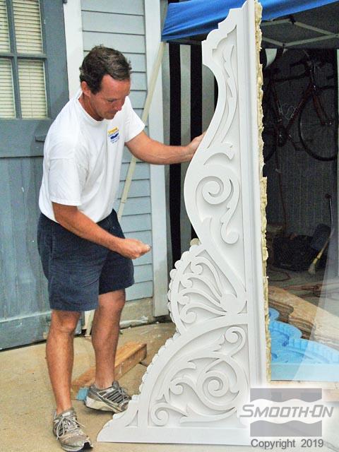
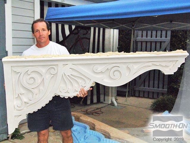
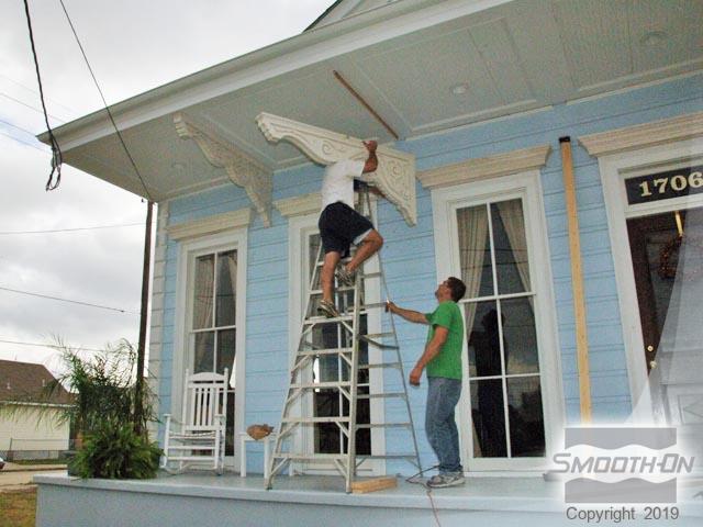
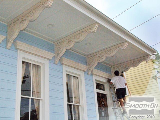
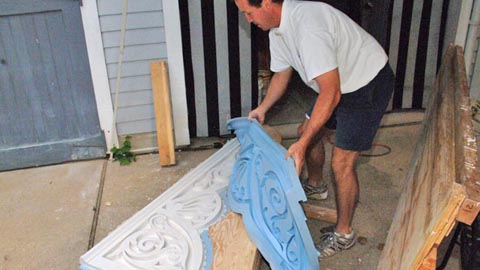
After Hurricane Katrina hit New Orleans, city native Chep Morrison used Mold Max® XLS II LOW SHRINKAGE silicone rubber to replicate an ornate bracket for an architectural restoration project near the Garden District.
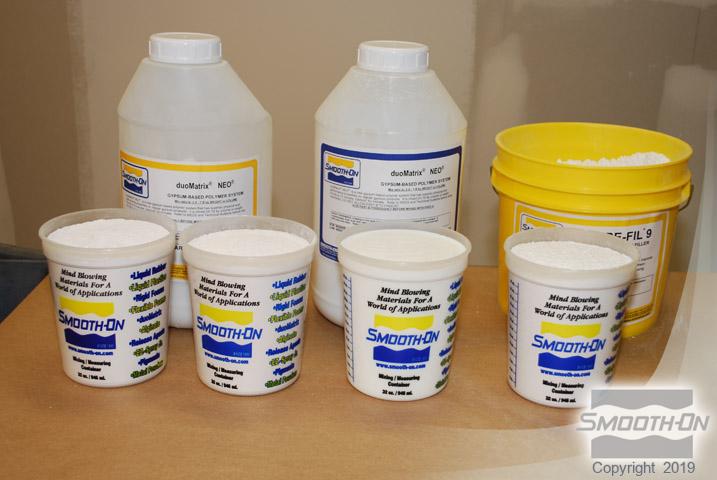
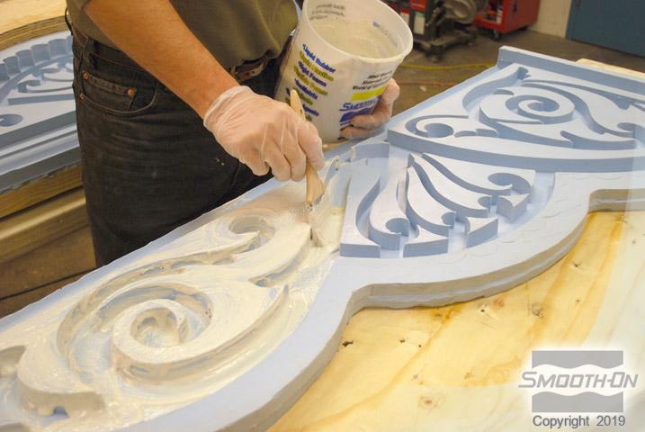
After the unique, two-part block-mold was made using a custom-shaped mold box, the ornate brackets were cast in a two-step process that involved coating the surface of the mold first using duoMatrix® NEO Polymer Modified Gypsum. This was done to create a hollow piece and reduce the overall weight of the casting.
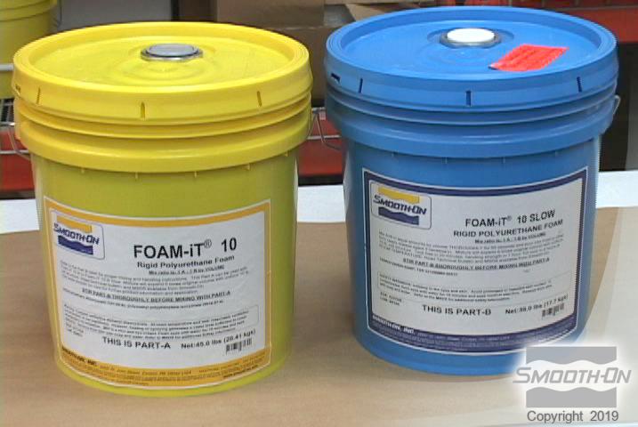
Once the duoMatrix® NEO was applied and allowed to cure, the second step involved backfilling the hollow castings to add dimensional strength and stability to the bracket structure. Foam-iT!® 10 SLOW is a 10 lb. / cubic foot expanding urethane foam that was used to backfill the hollow castings. Foam-iT!® 10 SLOW expands approximately 6 times it's original volume and cures to a rigid finish. After measuring and mixing the foam, it began to expand and fill in all the nooks of the interior aspect of the hollow casting and was allowed to cure at room temperature (73°F / 23°C).
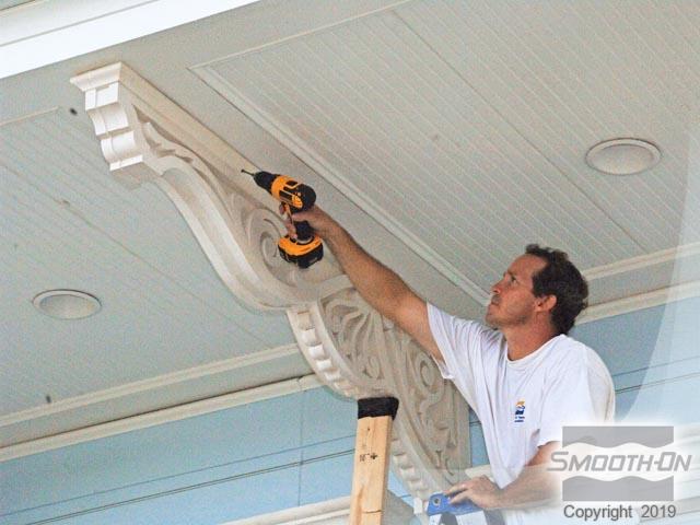
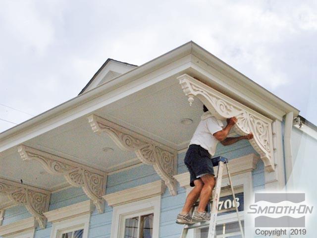
By using Mold Max® XLS II, Mr. Morrison could create many exact replicas of the original bracket, not only for this project but for future projects as well. In using duoMatrix® NEO and Foam-iT! 10 SLOW, the brackets display remarkable dimensional strength and stability, while maintaining an overall lightweight finish. Maintaining a lightweight finish enabled Mr. Morrison to easily install the ornate brackets, helping to reduce labor costs.
Materials Used in this Tutorial
- Plywood
- Kraft Paper
- Electric Saw
- Drill and Screws
- Turbine Mixer Attachment
- Oil Based Clay
- Mold Max™XLS II
- Foam-iT™ 10 SLOW
- Ease Release™ 200
- duoMatrix™ NEO
- Ure-Fil™ 9
- Vacuum Chamber
Step 1: Preparing the Model
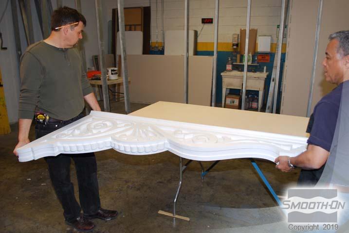
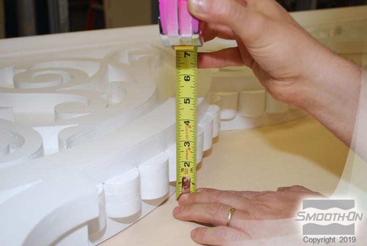
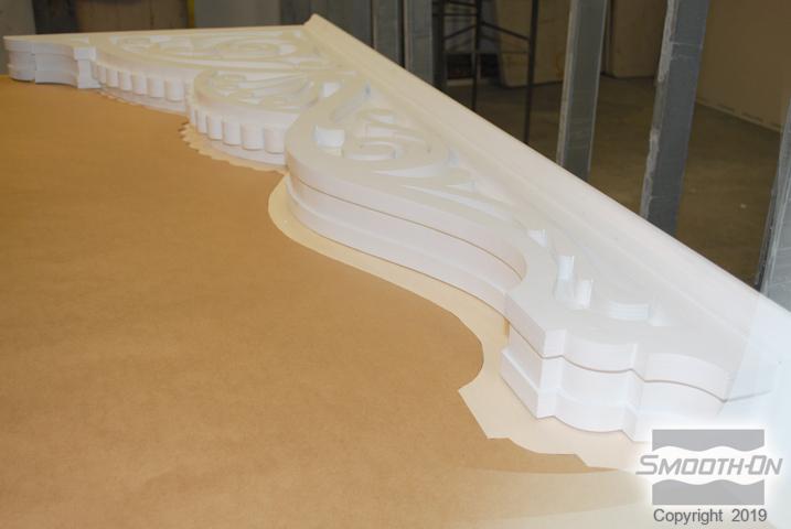
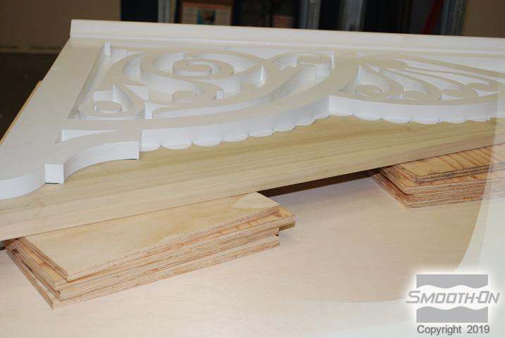
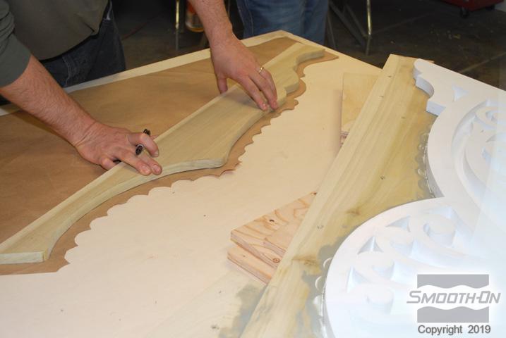
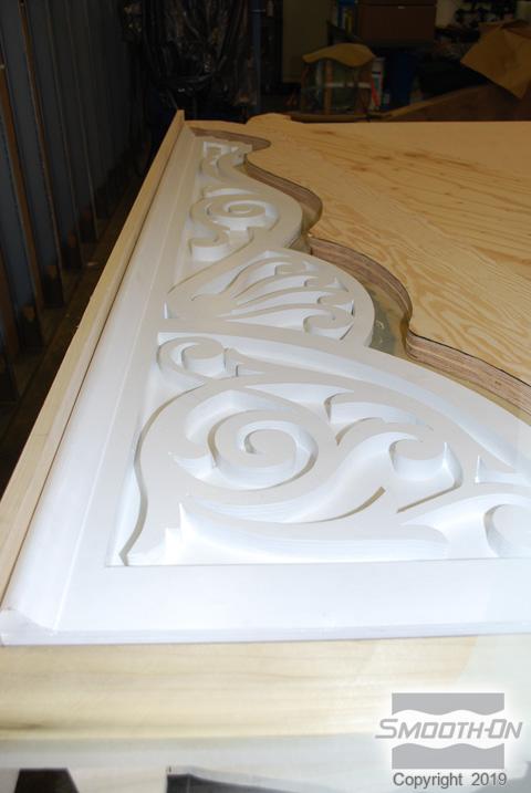
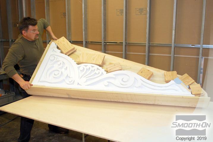
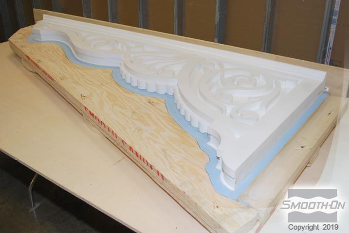
The painted wooden bracket (model) is placed on a flat level surface. The model is measured; dimensions are approximately 72'' x 30'' x 4'' (182cm x 76cm x 10cm). To make the 2-part mold, the model will be divided into two halves horizontally and a parting line will then be constructed.
Step 2: Creating a Pattern for the Mold Box
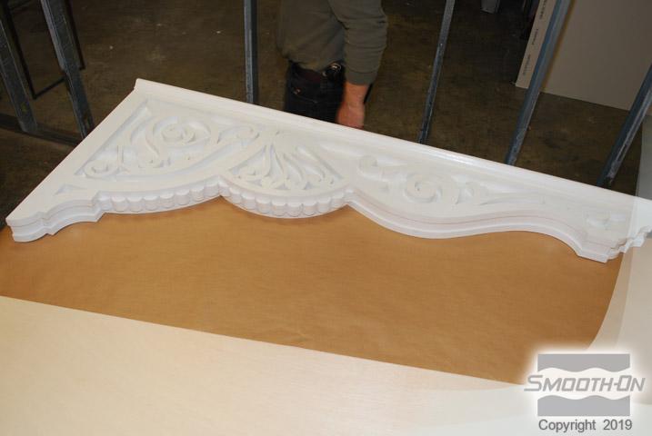
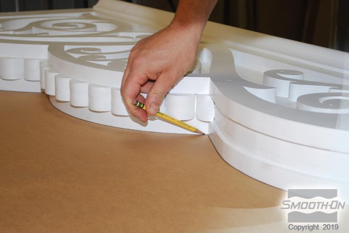
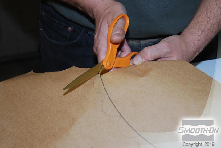
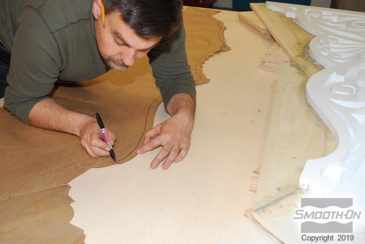
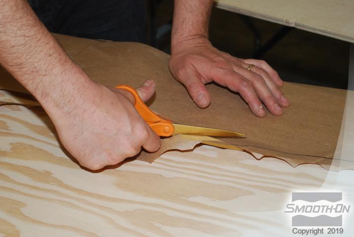
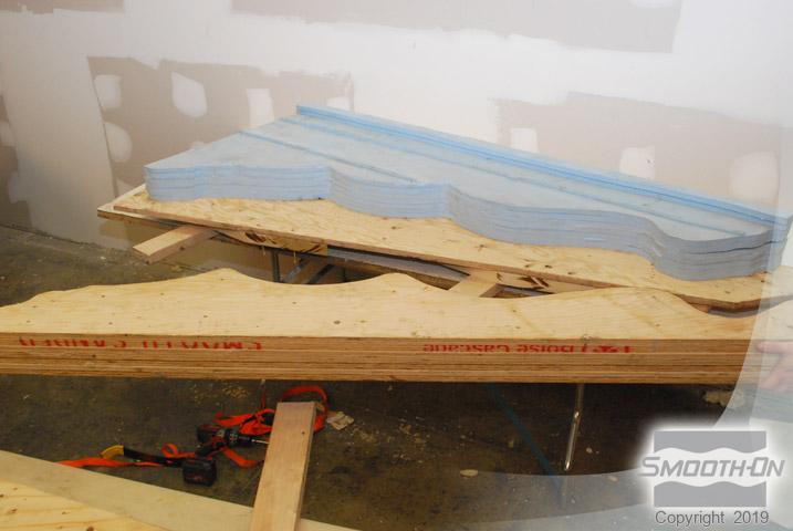
Craft paper is placed under the model and will be used to create a template for the parting line. The pattern is transferred onto the craft paper (template) with a pencil and scissors are used to cut out the template.
Step 3: Creating a Parting Line Wall
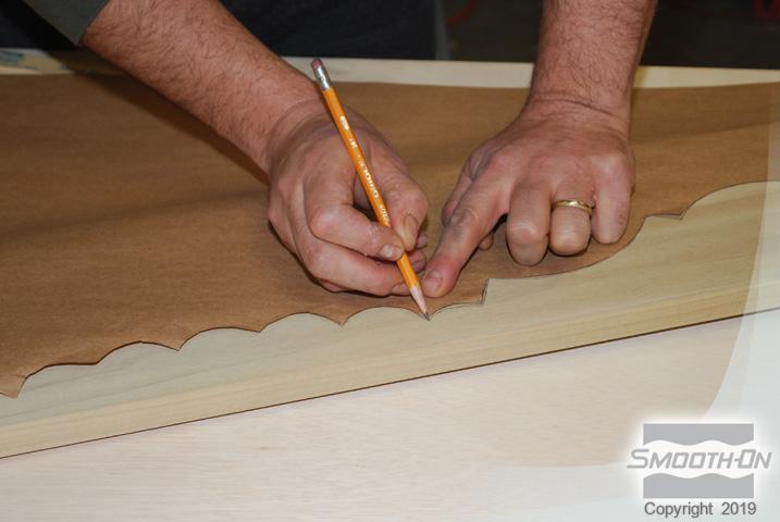
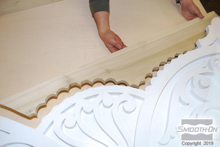
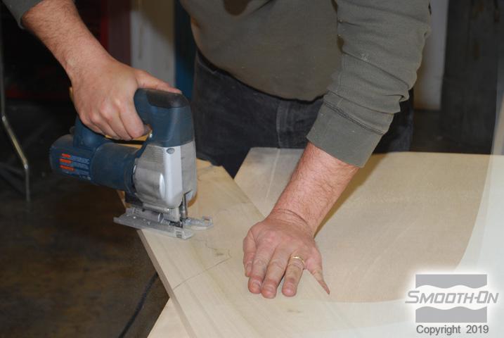
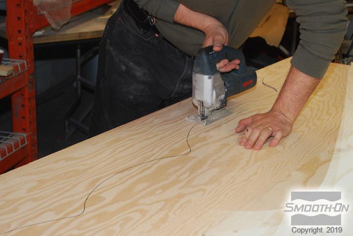
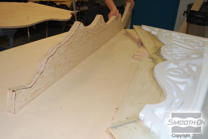
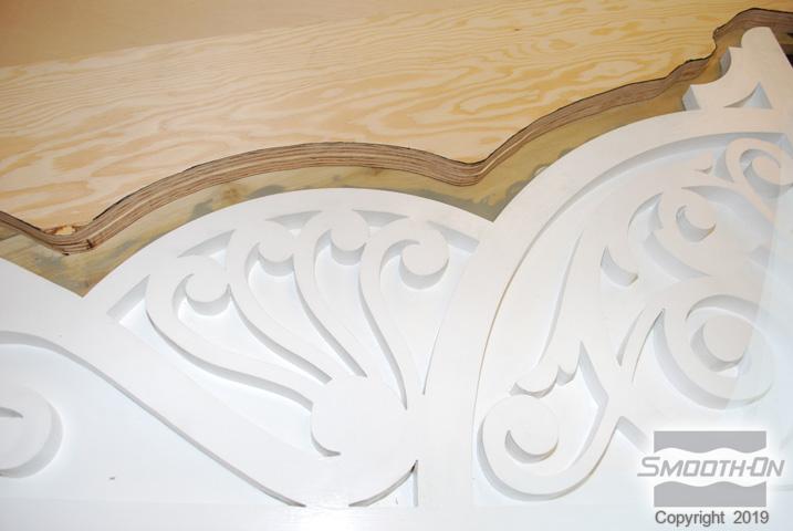
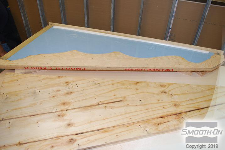
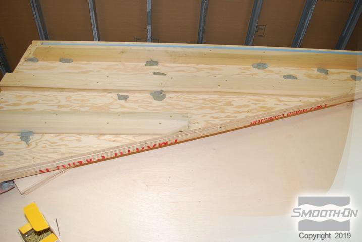
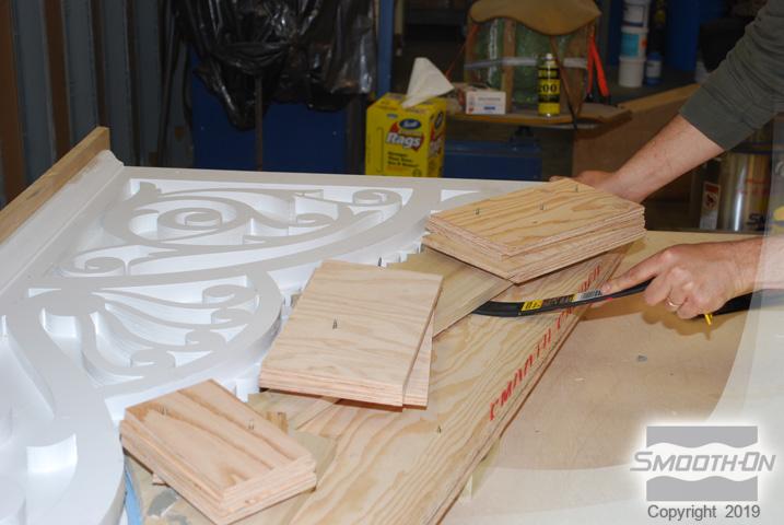
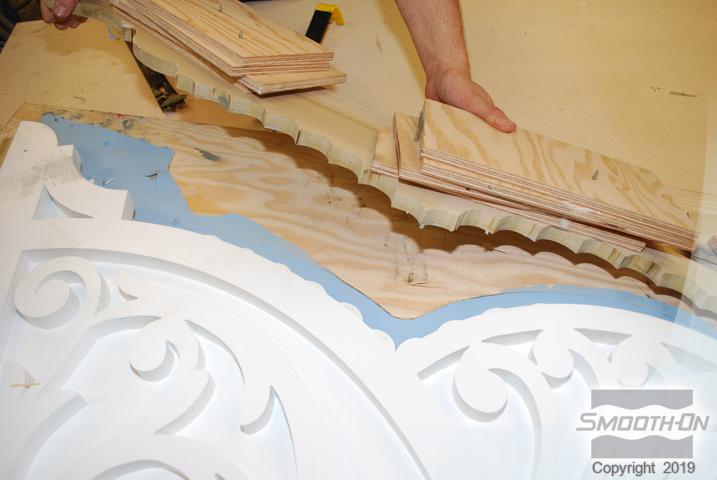
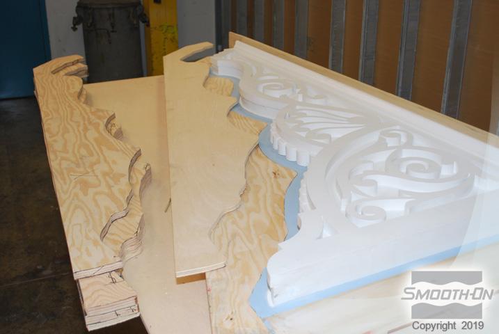
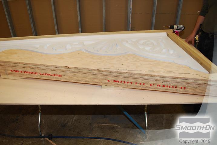
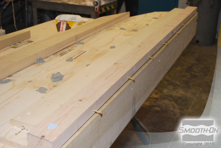
The pattern is then transferred onto a piece of wood with a pencil. A jigsaw is used to cut the wood, which will be used to establish the parting line. The wood parting line is elevated and secured in the correct position.
Step 4: Sealing the Parting Line Wall
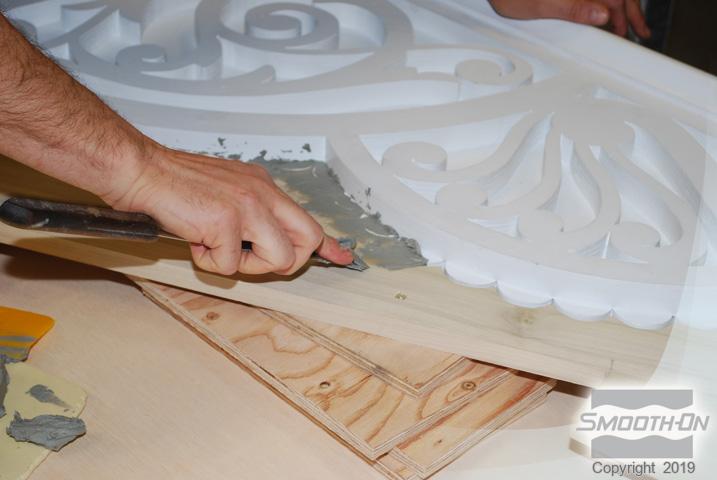
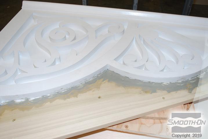
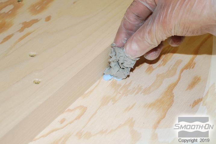
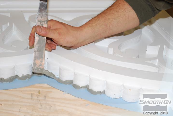
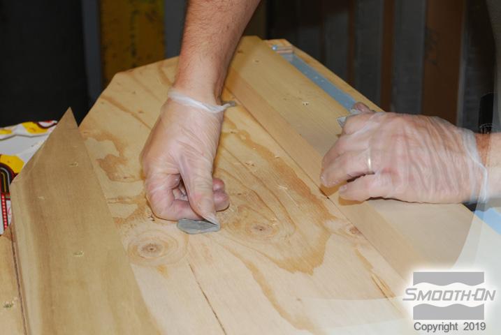
Non-sulfur based clay is used to fill any voids between the parting line and the model, and the clay is smoothed out.
Step 5: Creating Mold Box Side Wall Template
The original template is used to create a new template for the mold box side walls. The line is offset 2'' (5 cm) to provide enough space around the model to allow for suitable rubber mold wall thickness. Scissors are used to cut out the template.
Step 6: Creating Mold Box Side Wall
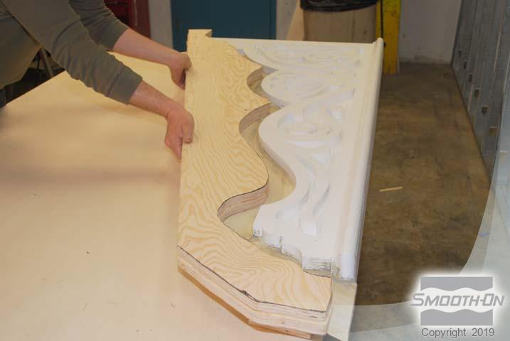
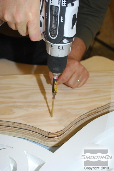
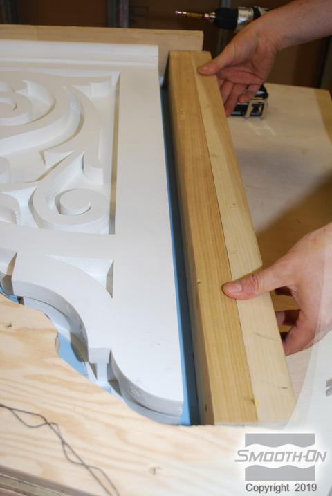
A jigsaw is used to cut the wood. Additional wood is then cut to build mold box side wall. Mold box side walls are then placed onto the wood parting line and secured. the space between mold box side walls and model allows for suitable mold wall thickness.
Step 7: Creating Mold Box Lid
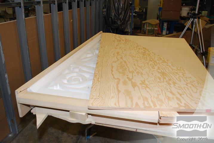
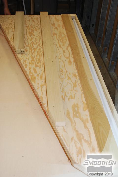
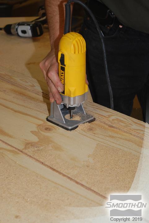
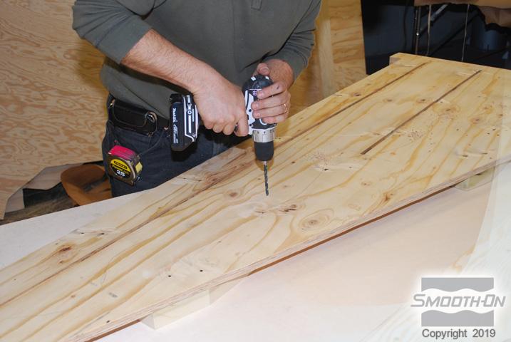
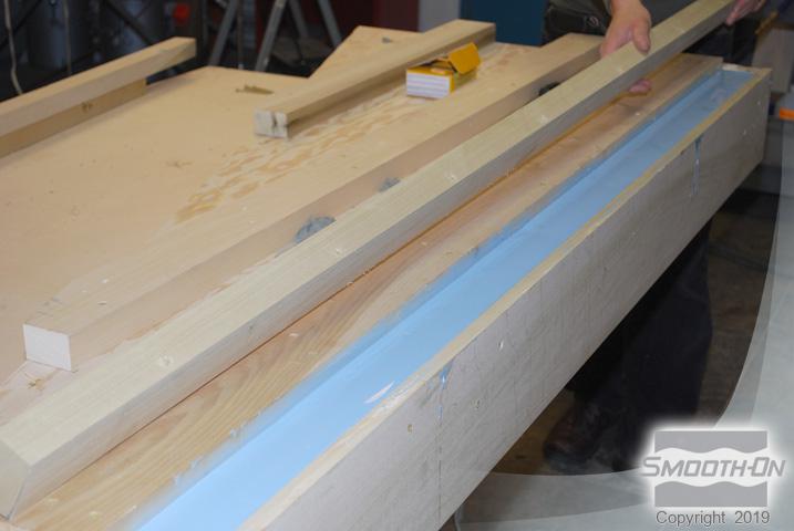
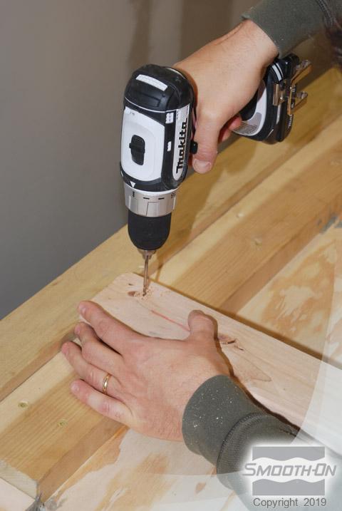
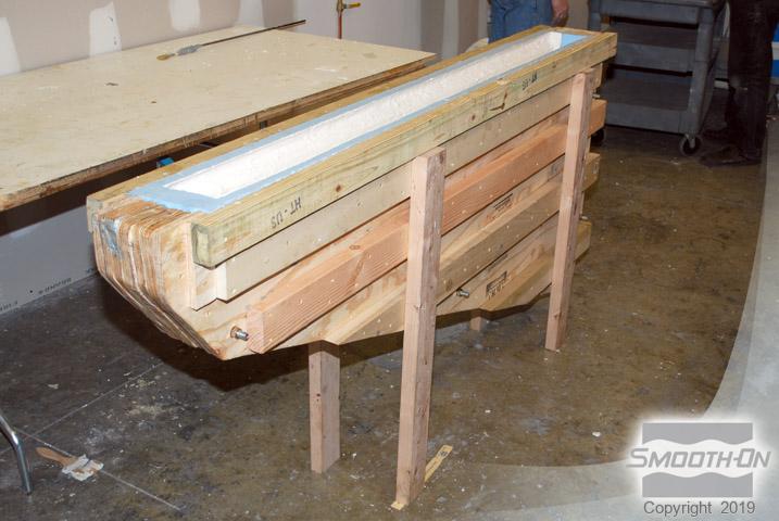
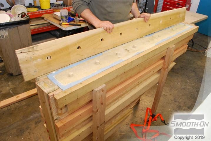
A mold box lid is constructed to contain the silicone rubber. The lid is reinforced with wood to provide additional support. Channels are routered into the mold box lid to function as a registration key for the rubber mold. Vent holes are drilled to allow air to escape as the mold box is filled. Additional wood is cut and attached to complete the mold box.
Step 8: Mixing Mold Max™ XLS II Silicone Rubber
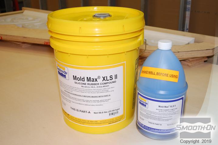
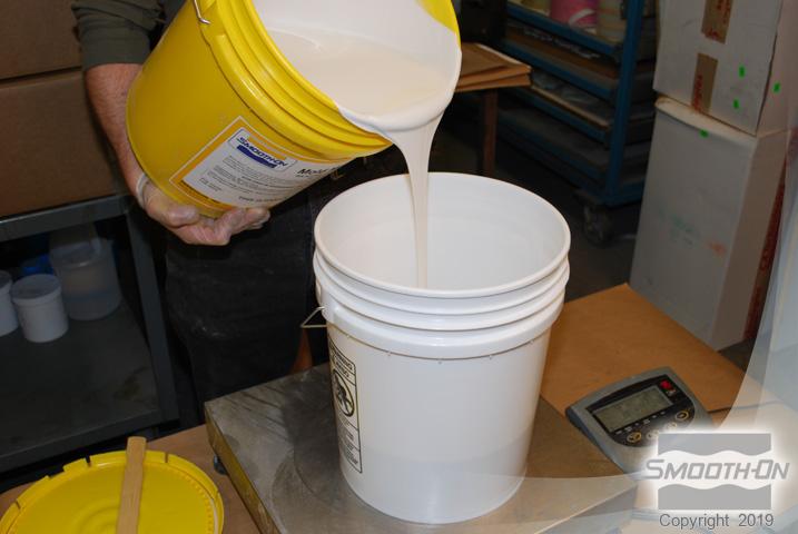
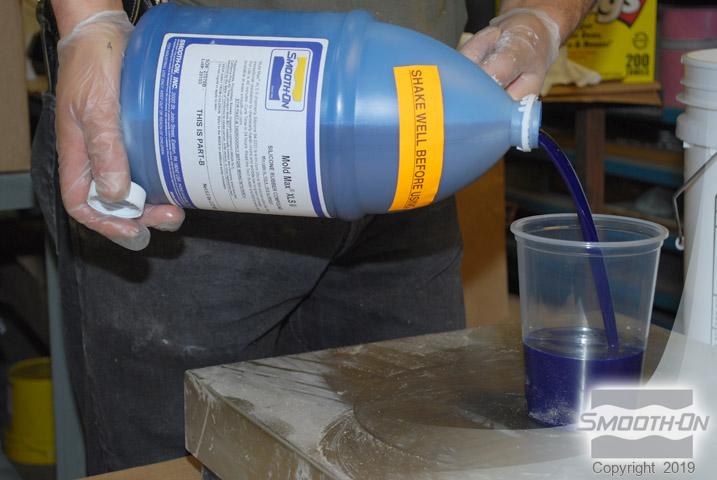
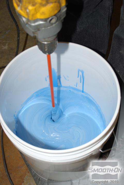
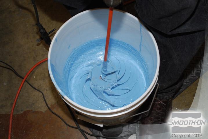
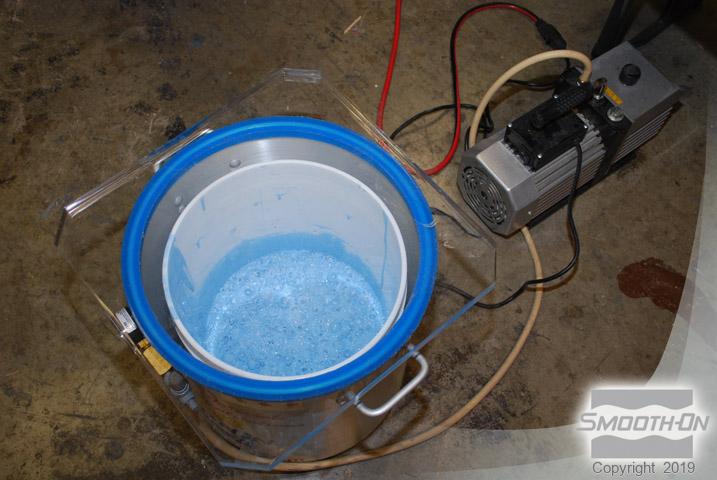
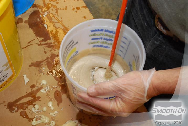
Mold Max™ XLS II is a silicone rubber that has a very low long-term shrinkage. Mold Max™XLS II has a mix ratio:100A:10B by weight. Using a gram scale, Mold Max™ XLS II Part B Being Measured. Mix Mold Max™ XLS II for at least 3 minutes Mold Max™ XLS II has a pot life of 40 minutes. After mixing, the rubber is vacuum degassed.
Step 9: Pouring Mold Max™ XLS II Silicone Rubber
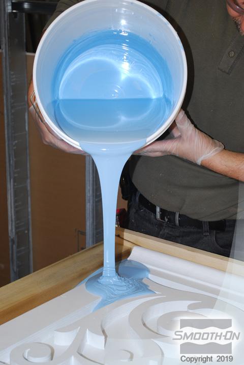
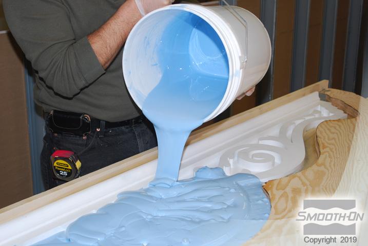
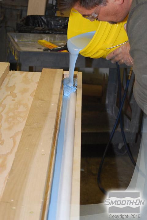
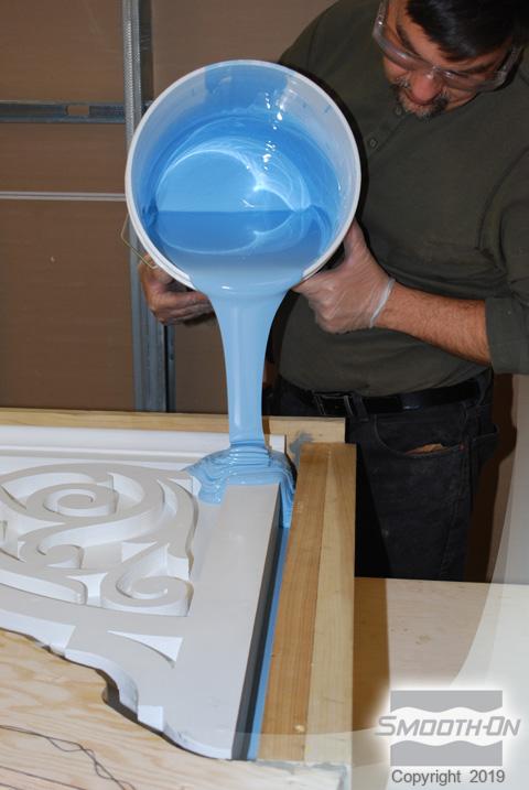
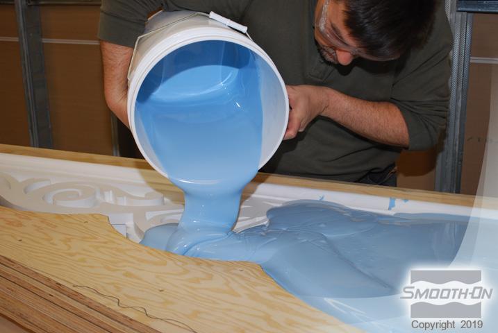
Mold Max™ is poured over the model until rubber is level.
Step 10: Placing the Mold Box Lid
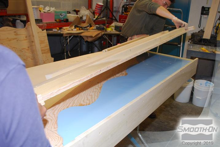
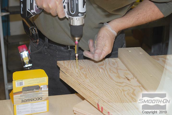
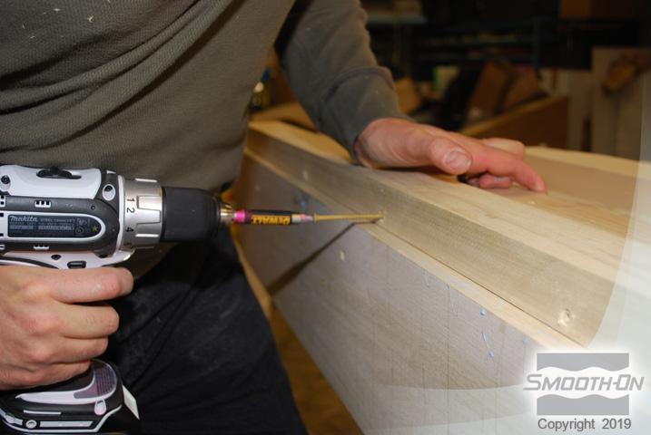
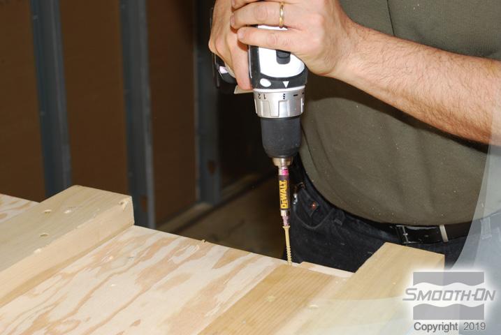
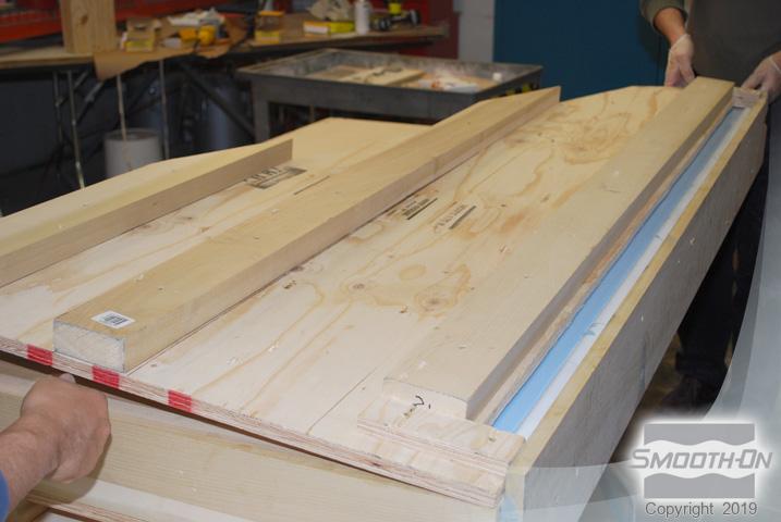
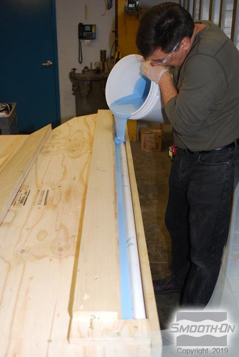
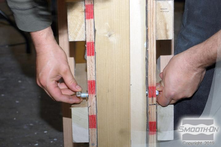
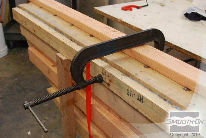
Mold box lid is placed over the silicone and secured with screws. Additional silicone is poured in the top of the mold box to fill the open void. Non-sulferoil based clay is used to plug pre-drilled vent holes. Additional wood is used to cap the mold box.
Step 11: Mold Max™ XLS II Is Set To Cure
Mold Box Cap is Secured with Screws. Let Mold Max™ XLS II cure for 24 hours at room temprature (73°F/23°C).
Step 12: Inverting mold and Preparing for Part Two of the Mold Max™ XLS II
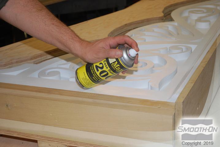
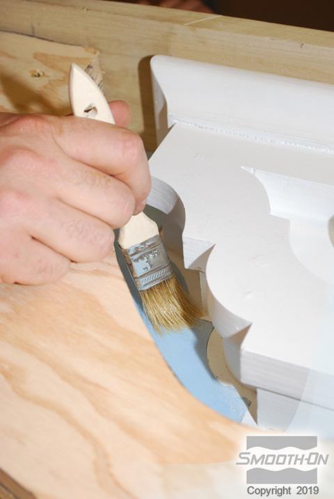
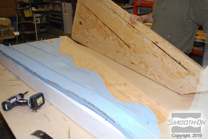
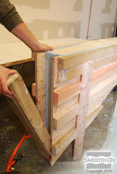
Mold box is turned over and the parting line wood and clay are removed from the model. Model in cured silicone ruber is thouroughly cleaned. Wood is cut to form mold box side walls and then secured with screws, additional wood is cut and attached on the sides to complete the mold box assembly. Ease Release™ 200 is sprayed to the cured silicone surface and then brushed into the detail. This prevents Adhesion between pours of rubber.
Step 13: Demolding
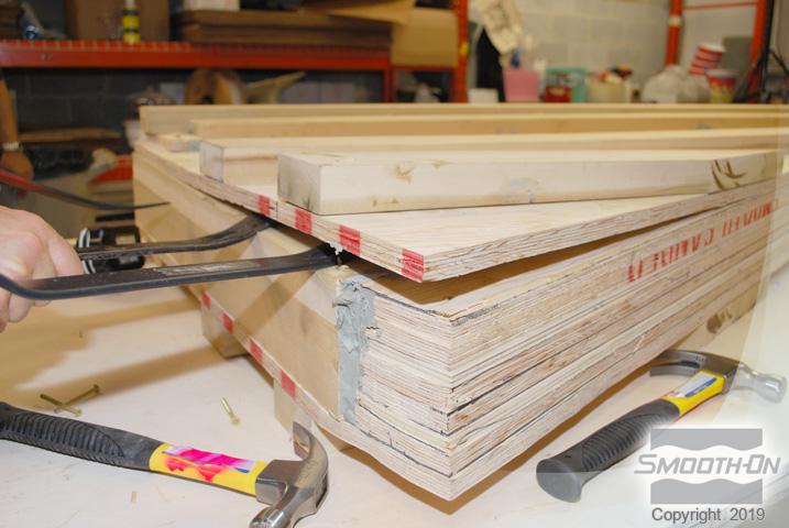
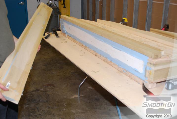
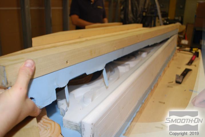
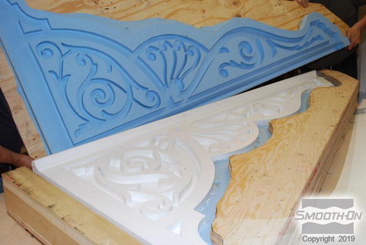
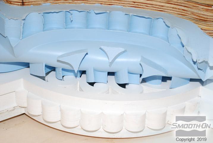
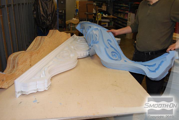
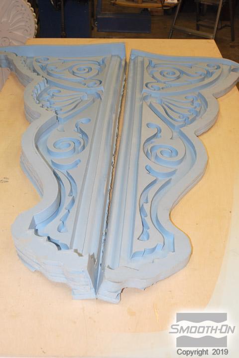
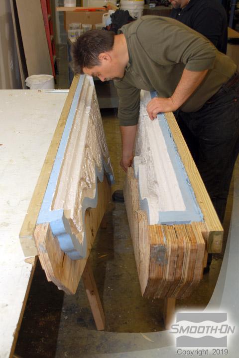
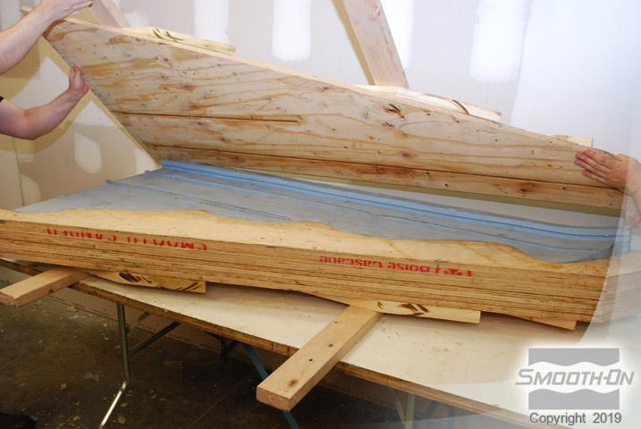
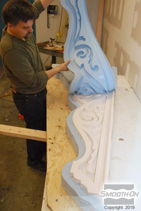
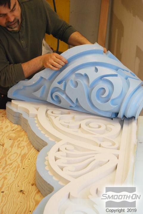
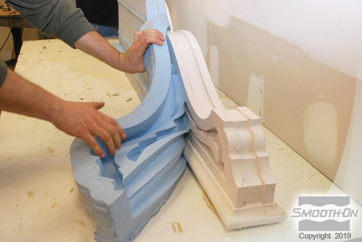
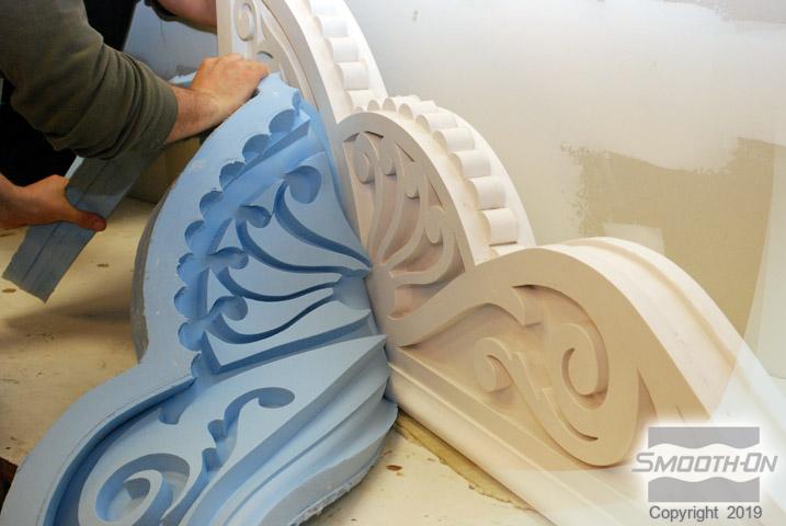
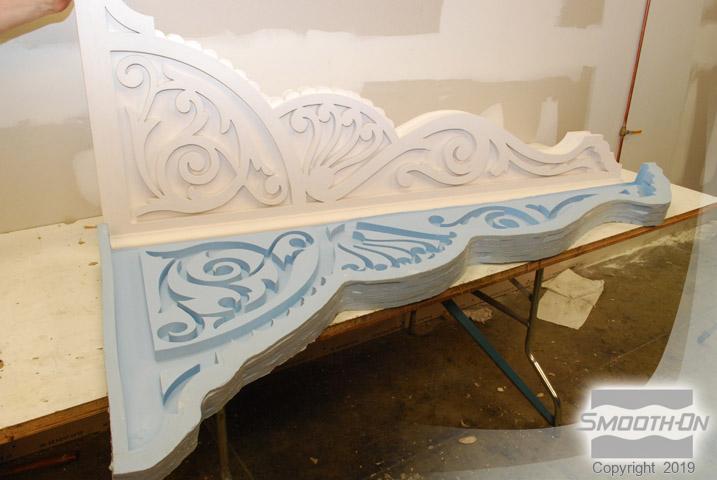
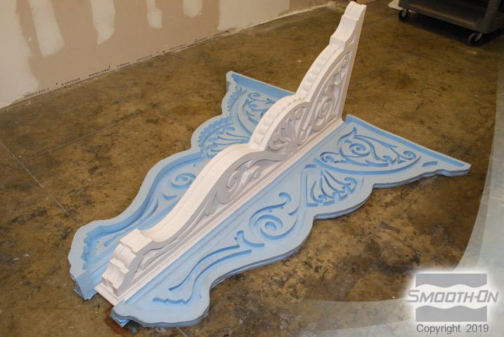
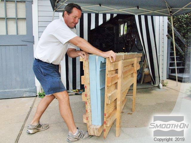
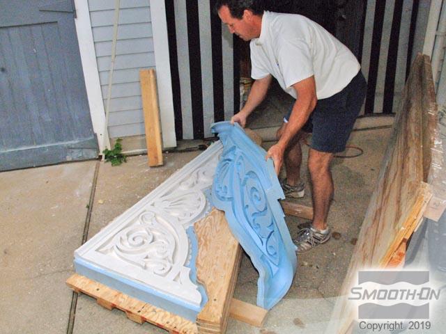
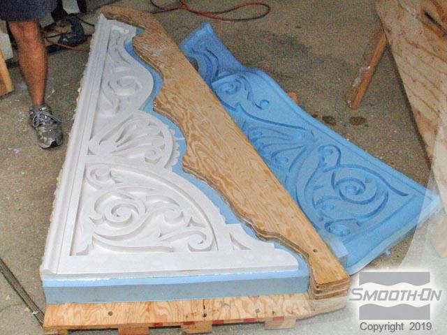
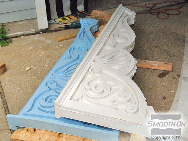
Screws are removed and the mold box is disassembled and the first half of the mold is removed. The mold box is then turned over and the second half of the mold box is removed. The final result of Mold Max™ XLS II captured excellent detail, now the mold is ready for casting.
Step 14: Applying Mold Max™XLS II
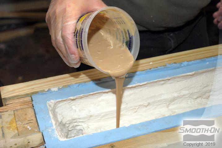
Mold Max™ XLS II measured 100A :10B by weight, after the material is dispensed it is then mixed and for at least 3 minutes and vacuum degassed. The rubber is poured over the model and the second-half mold box lid is placed over the rubber and secured with screws. Additional silicone rubber is then poured in the top of the mold box to fill the open void. Non-sulfur oil based clay is then used to plug pre-drilled vent holes. Additional wood is used to cap the mold box and Mold Max™ XLS II is set to cure for 24 hours at room temprature(73°F/23°C).
Step 15: Preparing the Mold for Casting
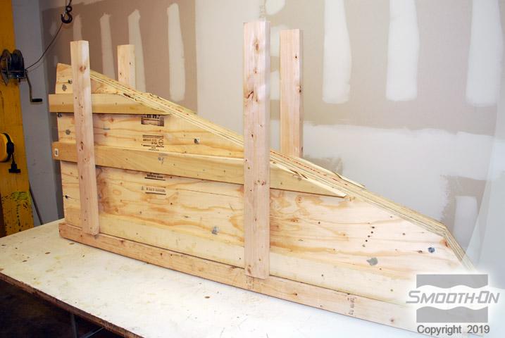
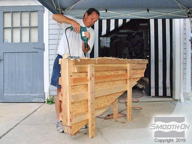
Wood legs are attached to the plywood lid to keep the mold assembly oriented vertically during casting.
Step 16: Casting DuoMatrix™ NEO
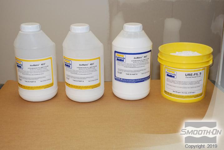
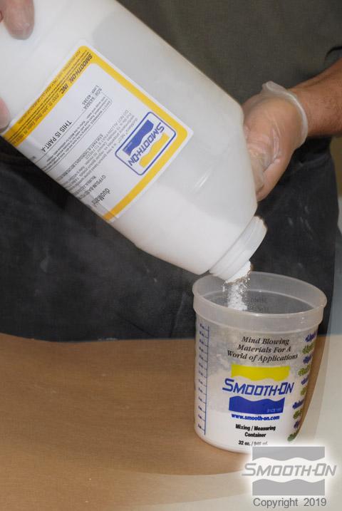
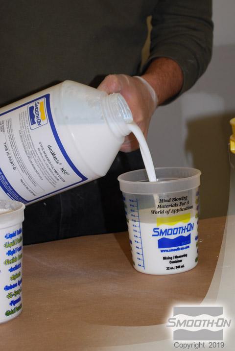
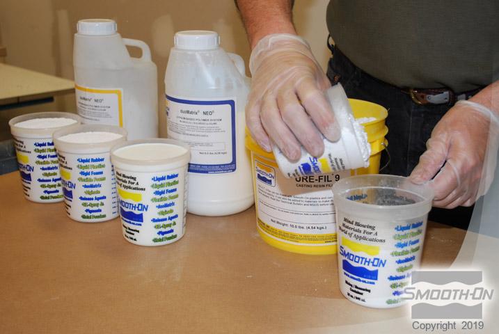
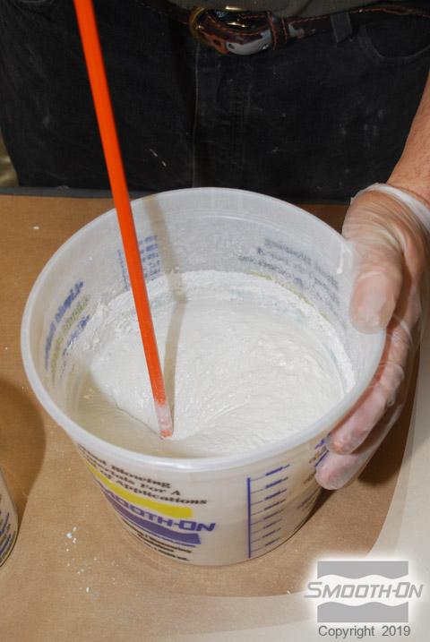
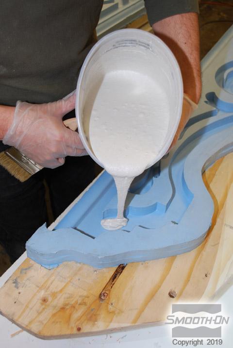
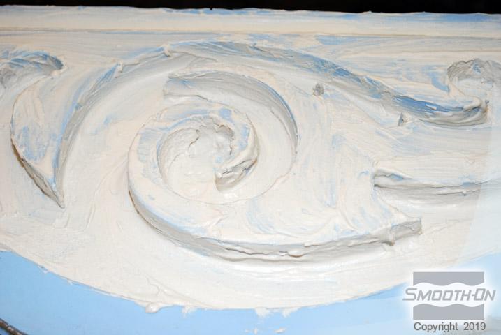
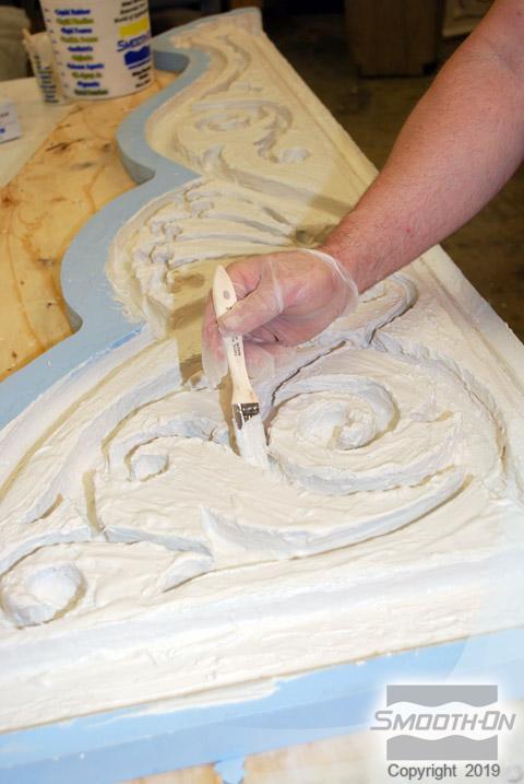
duoMaterix™ NEO is dispensed 2 Parts A; 1 Part B by volume, Ure-Fil™ 9 is dispensed and mixed thoroughly with a drill mixer into the duoMatrix™ NEO for thickening the mixture for easy brush on application. duoMaterix™ NEO is poured into the mold. Material is then spread onto the mold surface using a clean, disposable paint brushed duoMaterix™ NEO is applied to a thickness of 3/16" (4.7 mm). Material is then applied to the second half of the mold and both halves are allowed to cure for 90 minutes at room temperature (73°F/ 23°C).
After both halves are cured they are then joined and secured. Additional duoMatrix™ NEO is measured, mixed and poured along the seam to help join the two halves of the casting.
Step 17: Pouring Foam-iT!™ 10 Slow Rigid Polyurethane Foam
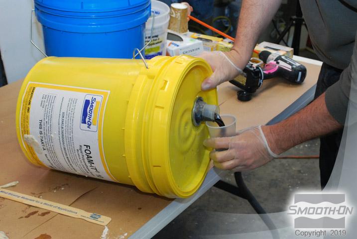
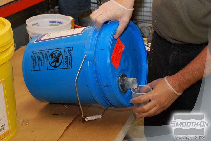
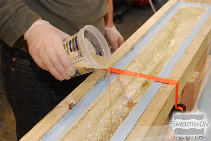
Foam-iT!™ 10 SLOW is dispensed 1A:1B by volume and mixed thoroughly with a drill and turbine Mixer attachment. The material is poured into the cavity and allowed to expand. Multiple small batches of foam are added to fill the cavity as need. A board pre-drilled with vent holes is placed over the mold box opening and secured to create back pressure. The material in the assembly is allowed to cure for 2 hours at room temperature (73°F/ 23°C).
Step 18: Demold
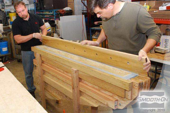
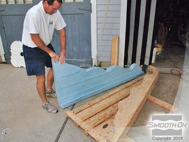
Mold Box is disassembled and rubber is slowly pulled away from casting. Casting is an exact lightweight reproduction of the original bracket. Mold Max™ XLS II is ready to be cast again and again.
Step 19: At the Job Site
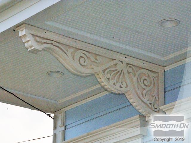
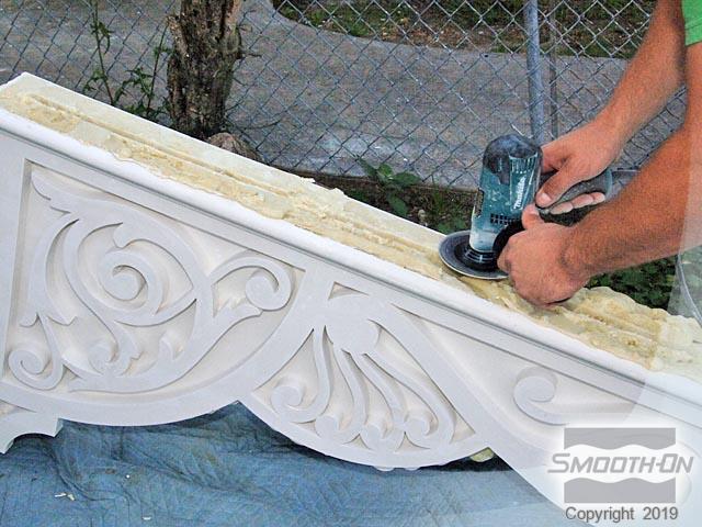
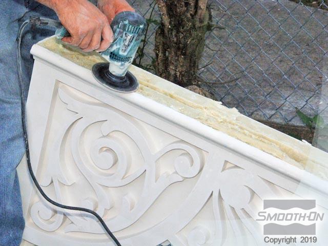
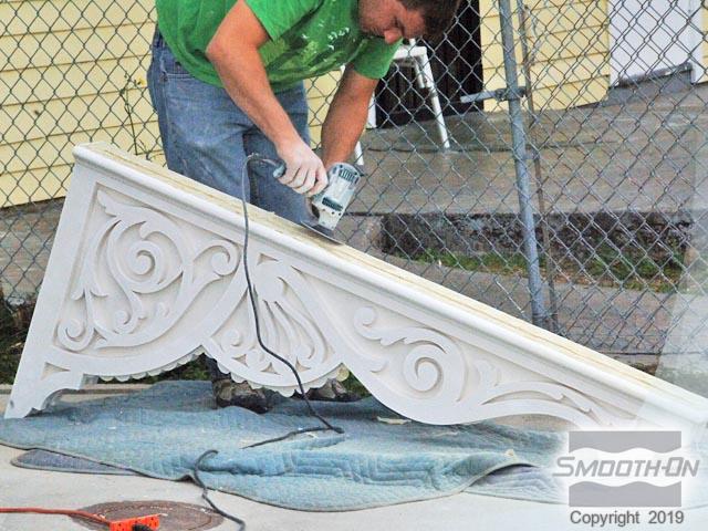
The Mold Max™ XLS II silicone rubber pulls away effortlessly and captures perfect detail. The casting comprised of duoMatrix™ NEO and Foam-iT!™ 10 SLOW is structurally lightweight but ultra strong and dimensionally stable. Before the brackets may be installed, excess Foam-iT! 10 SLOW is trimmed off with a grinder to level the surface that will press against the porch ceiling. Trimming the excess expanded foam will help prevent and gaps in between the bracket and the ceiling the bracket is then ready for installation.
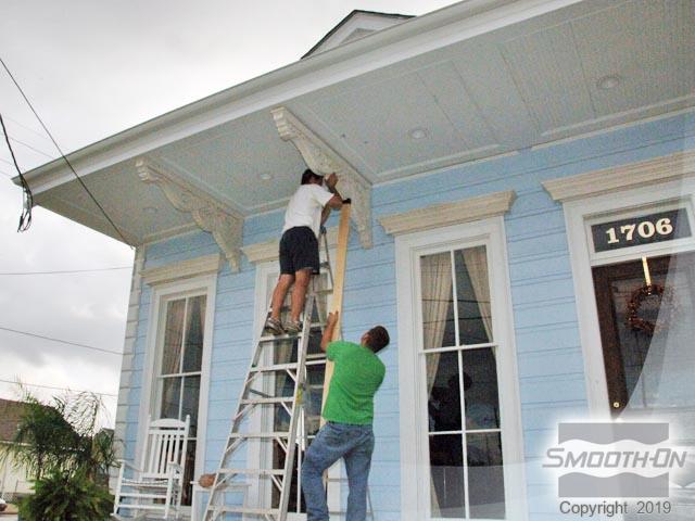
The Bracket is held in place using a brace and attached to the ceiling using anchoring screws. Multiple brackets are all cast from a single mold and installing the cast brackets only takes a few minutes. The house now displays an architectural charm that is unique to New Orleans.
